https://tse4.mm.bing.net/th?id=OIP.ZMZNB-1RV2n1N_yxvJ7wzgHaH1&pid=Api&P=0

Watching a Rocket stove or a pellet stove (as above), it becomes obvious that metering the fuel is a primary factor in achieving close to complete combustion. When too much fuel is introduced into the combustion chamber, the emissions of smoke increase almost immediately.

For the clean burning of biomass, the controlled metering of fuel seems to be as necessary as it is in the engine of an automobile. The rate of reactions (how fast the solid biomass is being converted into wood gas) is then matched with the corresponding amounts of Time, Temperature, and Turbulence required to minimize CO and PM2.5.

ARC has added Metering to Time, Temperature, and Turbulence while unsuccessfully searching the thesaurus for a synonym that starts with the letter T. Maybe someone can succeed where we have failed?

http://stoves.bioenergylists.org/stovesdoc/Reed/Pics%20in%20files.jpg
Forced draft mixing with 2nd air jets in Dr. Tom Reed’s WoodGas Stove at around 1,000C

Forced draft mixing with preheated jets of primary air reduced emissions of PM 2.5 by around 90% in our stove tests with the Jet-Flame. Would adding secondary air jets further decrease emissions?

Secondary Air Works in TLUDs

Lefebvre, Vanormelingen, and Udesen examined secondary air jets air in cylindrical combustion chambers and describe most successful patterns of penetration depth. Jet penetration lengths approaching the middle of a cylindrical combustion chamber resulted in a maximum reduction of PM2.5 emissions. An increase in the number of jets created more thorough mixing. It was important to have the jets meet in the middle, but with minimal necessary force, to ensure highest temperatures and highest velocity of hot gases to the pot.

Forced draft secondary air jets can decrease the upward draft in a cylinder. Jets of air aimed horizontally into the flame most efficiently create mixing. But even when aimed upwards toward the pot they create a ‘roof of air’ that slows the draft by creating a high-pressure front.

Regardless of the velocity of secondary air flow rates, or the angle at which air is injected into the combustion chamber, supplying secondary air also tends to significantly lower the temperature. For this reason, using a minimal amount of air was found to be best. There is a reported balance resulting in optimized mixing, draft, residence time, and temperature. (Lefebvre, 2010) (Vanormelingen, 1999) (Udesen, 2019)

How Do We Add Secondary Air Successfully to Rocket Stoves?

One obvious difference between TLUDs and Rocket stoves is the large fuel door in the side of the Rocket stove. A TLUD is an open topped cylinder with a small amount of primary air entering the batch of fuel from below the packed fuel bed. In the TLUD, the fuel is initially dropped into the cylinder, while in a Rocket stove horizontal sticks are pushed into the combustion zone through a fuel door. The pressure/volume of secondary air jets introduced into a Rocket stove may be limited because the high-pressure front can create a backdraft that sends smoke out of the fuel door.

Supported by funding from The Osprey Foundation, ARC is currently experimenting to determine: 1.) How much pre-warming can be achieved and 2.) What is the most effective pressure/volume for secondary air jets in a forced draft Rocket stove.

by Kirk Harris

Blade cross sectional shapes:

There are several main physical principles that can be used to make a functional cross-sectional shape.

  1. The gas enters the stationary fan vertically from below, and should leave the fan at as flat an angle as possible.
  2. Deflection:  The side of the blade that faces the oncoming gas deflects the gas to change its direction.
  3. A space between the blades can allow gas to pass upward without deflecting it, reducing the stationary fans efficiency.
  4. The Coanda effect can be used on the side of the blade facing away from the oncoming gas to deflect the gas.  The Coanda effect states that a stream of gas moving parallel and close to a surface will experience a force holding it close to the surface.  This force results from Bernoulli’s principle.  The moving gas is at a lower pressure then the atmospheric gas next to it, and so is pushed toward the surface.  The surface blocks atmospheric pressure from pushing back.

 Three shapes of blade cross-section to consider:

Straight angled

The gas on the bottom side of the blade is moderately deflected and leaves the blade at a bad angle, reducing swirl.  The gas on the top side of the blade cannot form a Coanda type connection to the blade because it is not flowing parallel to the surface.


Straight bent

The gas on the bottom side of the blade is moderately deflected, leaving the blade at a bad angle.  The sharp bend in the blade slows and disrupts the gas flow.  The gas on the top side begins by moving parallel to the blade surface, and so can attach to the bottom half, but cannot stay connected because of the sharp bend.  Sharp bends destroy the Coanda type connection.


Smooth curve

The gas on the bottom side of the blade is fully and smoothly deflected to the horizontal direction.  The gas on the top side of the blade begins by moving parallel to the surface, and so can form a Coanda attachment to the blade.  Because of the Coanda effect, the gas can follow the smooth curve of the blade to a flat exit path.  Note that the leading edge of the blade is at a right angle to the trailing edge.


Draft (buoyancy) vs. the Coanda effect

The gas moving horizontally on top of the blade is subject to two competing forces, the draft and the Coanda effect.  The draft tries to direct the gas upward while the Coanda effect tries to keep the gas attached to the blade going horizontally.  If the gas speed is slow and/or the connection of the gas to the blade is weak, the draft wins and the gas breaks away from the blade.  The gas may be split between the two, some gas going each direction.

The gas deflected by the previous blade can join the Coanda effected gas on the current blade, countering the draft induced upward motion and improving the swirl.


Blade Construction

The simplest stationary fan for creating swirl is made from a single round disk of sheet metal. 

There may be 4 or more blades, but I will describe a 6 bladed fan, which works best for me.  Draw a small circle in the center which will hold the blades together.  Draw 6 radial lines from the center, outside the small circle evenly spaced at 60o each.  Cut the radial lines to the small circle.  If the fan is to be mounted on a shaft, drill a center hole of the appropriate size.

Bend the 6 blades as shown with red lines around the point of intersection of the radial lines with the small circle.  Make the curve smooth and round so the gas can stay connected using the Coanda effect.  The lower edge of the blade should point straight down, the upper edge horizontal.

The stationary fan will cause flow resistance for the gasses.  This will slightly reduce the highest power level of the stove.  Lower power levels are more sensitive to flow resistance and the flame may go out.  A small slit, as shown in red, can reduce the flow resistance and allow higher and lower power flames.  The blade must be bent as shown, from the end of the slit.

There will be an open space between the blades which will allow gasses to pass upward without being effectively deflected, reducing swirl.  This type of fan can work quite well, but can be improved.

An improved version which eliminates the gap can be made from two circles.  Mark three evenly spaced blades at 70o on both circles.  Cut out the 50o space between.  Make a short cut on the red lines.  This will make room to place one circle on top of the other to form one fan with 70o blades.  Spot weld the two circles together in the small center circle.

Bend the blades as before around the red lines, but with the center at what would be the 60o blade point.

The finished fan will not have the gaps and will be more efficient, especially for slow moving flame gas. 

Flame gasses may escape deflection around the ends of the blade.  This can cause incomplete combustion and increased particulates.  This problem may be fixed by extending the blade beyond the flame, placing something to block the gasses from escaping, or by raising the center of the fan and bending the blades slightly downward as shown along the dotted lines (thus directing the flame inward).

Illustration of a Reaction Vessel and a Burner for a TLUD stove

The Rocket stove requires forced draft to create sufficient mixing in the flame to achieve Tier 4 for PM2.5. In addition, when sticks are pushed too fast into the Rocket, too much wood gas enters the combustion zone and a lot of smoke is emitted. Metering of the fuel is necessary to keep the Rocket stove even moderately clean burning. Unfortunately, that is unlikely to happen in real life.

On the other hand, the TLUD supplies a constant amount of wood gas into the combustion zone. A five inch in diameter reaction vessel produces around 4kW of energy (5 liters of water boils in about 20 minutes using a pot skirt with a 6mm gap).

The emissions of CO and PM2.5 can be very low in a natural draft TLUD when:

  1. The primary air controls the rate of reactions (how fast the wood pellets are turned into wood gas).
  2. The jets of pre-heated secondary air provide sufficient mixing of wood gas, flame, and air by completely covering the top of the fuel bed.
  3. The burner section allows sufficient Temperature, Time, and Turbulence to complete the combustion process.

Nothing is perfect. The TLUD, whether forced draft or natural draft, has trouble achieving enough Turn Down Ratio to simmer food efficiently. It’s also generally necessary to burn pellets to lower emissions to Tier 4 levels. At the same time, we love to cook on TLUDs and it is great not having to constantly adjust the fuel!

As Dr. Tom Reed said, “Now you’re cooking with the real natural gas.”

Jets of air at the top of a SupaMoto TLUD chamber cause flames to cover a bed of burning biomass pellets.
The SupaMoto Forced Draft TLUD

Before starting to develop cleaner burning cook stoves in the 2013-2015 DOE project, ARC researchers completed a survey of best performing existing stoves. Improving combustion efficiency to protect health (and climate) has continued as various cook stove organizations have worked tirelessly to meet the WHO 2015 PM2.5 Intermediate Emission Rate Target of 1.75mg/minute, calculated to protect health in homes using biomass to cook.

The results of the survey are described in Clean Burning Biomass Cookstoves, 2nd edition, 2021.

  • With a 6mm channel gap pot skirt, many stoves scored close to 50% thermal efficiency.
  • TLUDs were not able to achieve enough Turn Down Ratio (TDR) to simmer water.
  • Burning wood does not emit much CO so meeting the WHO CO Target (.35g/min) was easy.
  • Forced draft TLUDs scored between 2mg/min PM2.5 to around 5mg/min.
  • Stoves with chimneys met the aspirational WHO PM2.5 Emission Target of 0.23mg/min since the smoke was transported outside.

SupaMoto Forced Draft TLUD Bests WHO Goals

The new SupaMoto stove from Emerging Cooking Solutions with combustion technology from partner company Zemission has made great progress! For information contact Mattias Ohlson at: mattias@emerging.se. As seen below, in Water Boiling Tests at ARC, the SupaMoto Forced Draft TLUD achieved:

  • 51% to 56% thermal efficiency (without pot skirt)
  • 0.1g/min to 0.6g/min for CO
  • 0.19mg/min (simmer) to 1.11mg/min (high power) for PM2.5
  • The temperature corrected time to boil the 5L of water was fast, about 18 minutes

As in the FD TLUD Mimi-Moto stove, turn down in the Supa-Moto is achieved by inserting an accessory into the combustion chamber. The Supa-Moto Turn Down Ratio (TDR) varied between 1.91 to 2.11.  When a lid is used on a pot, a TDR of around 3 saves more fuel when a lower firepower is needed to simmer food to completion. Reducing the forced air jets in a TLUD does not create sufficient TDR.

It is so gratifying to witness progress! I never thought that we would see a biomass stove come so close to meeting the aspirational PM2.5 WHO Emission Rate Target.  To test a stove that easily meets the Intermediate PM2.5 Target is amazing. Mattias and the Zemission team have moved TLUD technology forward and it is a very valuable achievement!

Thank you for your work! Learning how to cleanly combust biomass has important ramifications in all parts of the world now that climate change reinforces the importance of renewable biomass as a health and climate friendly energy source.

Kirk Harris has been investigating TLUDs for decades and, as far as I know, his natural draft TLUD burning pellets achieved the lowest natural draft recorded score for PM2.5:  0.7mg/minute at high power (Lawrence Berkeley National Laboratory). This video shows Kirk in China at Shengzhou Stove Manufacturer where Mr. Shen built a copy of his stove to start the process of possibly manufacturing it.

The fascinating aspect in the video is how fast the flame is swirling, keeping the flame below the level of the pot and increasing dwell time.

Adding a fan shaped static mixer between the hole in the concentrator ring and the bottom of the pot has become commonplace in various TLUDS since Kirk invented the technique. We recently added a fan shaped static mixer in a natural draft TLUD to get rid of creosote. The tars were burned up in the hot, swirling flame.

Keeping the flame below the cold surface of the pot is always helpful and can be achieved with the Jet-Flame and in both natural draft and forced draft TLUDs.

To last long enough for commercial/carbon success, the combustion chamber has to be made with cast refractory ceramic. Making the static mixer and combustion chamber from cast refractory ceramic dramatically increases longevity. The Oorja stove in our lab has lasted for about 20 years!

I imagine Dr. Tom Reed smiling in heaven as the stove community moves closer to optimization with:

  • clean burning pellets 
  • a well-engineered TLUD 
  • a refractory ceramic combustion chamber 
Dr. Tom Reed, Dr. Alexis Belonio, Dr. Paul Anderson and Kirk Harris have refined TLUD technology

A natural draft TLUD can be as clean burning as a forced draft TLUD burning wood pellets. On the other hand, a natural draft Rocket stove needs a fan to be clean burning.

Dr. Tom Reed’s forced draft (FD) Woodgas stove achieved an emissions rate of 2mg/min of PM2.5 with pellet fuel (ARC, 2015). The Kirk Harris natural draft (ND) TLUD emitted 0.7mg/min of PM2.5, when tested at Lawrence Berkeley National Lab with pellets.

WHO Intermediate Emission Rate Targets

Unvented stoveVented stove
PM2.51.75 mg/minPM2.5   1.75 mg/min
CO 0.35 g/minCO   1.45 g/min

ND TLUDs tend to be pretty tall to generate necessary draft. A FD TLUD can be shorter since the fan creates the draft. Taller ND TLUDs can be expensive to manufacture. Precise control of primary air enabled a 3 to 1 turn down ratio in the Harris ND TLUD, difficult to achieve in a FD TLUD. (The FD Mimi-Moto, for example, has two combustion chambers, small and large, to provide cooks with high and low power).

Modern ND TLUDs

  • The primary air is adjusted to control the rate at which pellets are turned into combustible gases.
  • The secondary air jets cover the fuel bed.
  • A hole in the concentrator plate above the secondary air jets forces the flame into a vertical cylinder.
  • The cylinder of flame then enters static devices that create further mixing of air, flame, and gases.
  • The flame is shortened and does not touch the bottom of the pot where gases can condense into smoke.
Static mixers in the Kirk Harris 0.7mg/min PM2.5 ND TLUD
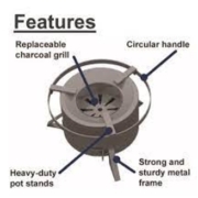
Typical Charcoal Stove
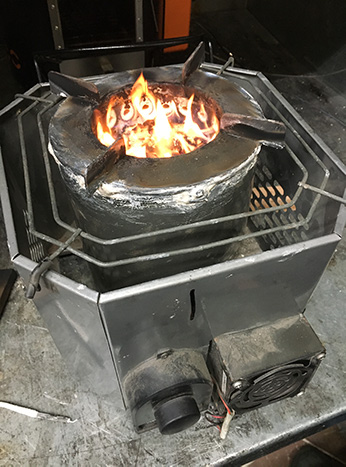
Oorja FD TLUD

Charcoal stoves are batch loaded like TLUDs (top loaded up draft stoves), but they differ greatly in how air flow is used to encourage combustion. A charcoal stove has lots of primary air blowing up into the fuel. A TLUD uses a small amount of primary air to create a relatively constant amount of woodgas that is then combusted by a mixture of secondary air and flame above the fuel bed. The large amount of primary air in a charcoal stove tends to create the fire underneath the fuel, while the secondary air jets in a TLUD concentrate the fire above the batch of fuel.

If a TLUD allowed as much primary air as a charcoal stove into the bottom of the fuel bed, too much wood gas would be made and the TLUD would be smoky. I wonder if charcoal stoves could be patterned after TLUDs? Could a charcoal stove be top lit with jets of secondary air and flame on top of the batch of fuel? Would such an arrangement result in better performance? Would added secondary air in a charcoal stove maintain the fire on top of the fuel that would burn up the woodgas (predominantly CO in a charcoal stove)? Might this increase heat transfer efficiency since the temperatures (convection and radiation) might be hotter?

When Sam Bentson and Ryan Thompson studied how to improve charcoal stoves in the DOE 2011 project, they found that adding pre-heated natural draft jets of air did help to create more flame where it’s needed, right under the pot. Unfortunately, they also experienced that charcoal makes less flame than wood and covering the entire top of the fuel bed with flame (as in a TLUD) is difficult. Forced draft secondary air might be more successful, especially since charcoal stoves are usually short and do not generate needed velocities. To be most effective, the jets of air/fire should meet in the middle of the combustion chamber and cover the entire fuel bed. It seems to be best to use the minimum velocity necessary since too much air only cools the fire (Udeson, D.J., 2019, University of Washington).

We’ll try it and report on the results.

Charcoal Stove Design Principles (Ryan Thompson)

  1. Size the combustion chamber for the required task. Whatever fuel is loaded into the stove will be burned at a rate proportional to the amount of air made available to it. In most cases, more fuel means higher firepower because there is always excess air. For small amounts of food/water, where not much power is required, either load a small amount of fuel into the stove, or use a stove with a small combustion chamber. For cooking lots of food at once, use a stove with a big combustion chamber.
  2. Charcoal stoves can have a high turn-down ratio. If the primary air supplied to a charcoal fire is reduced close to zero, the fuel will still keep burning. When the air supply is increased, the firepower will also increase. Normally there is a spike in CO when the air supply is increased sharply, but it tends to stabilize once the firepower comes back up.
  3. Use pre-heated secondary air jets to burn up the CO. Most charcoal stove designs have air coming in from the bottom and sides of the fuel bowl. The air must pass through the burning charcoal before it gets to the top of the fuel where the CO is being emitted. If hot air is added above the charcoal, it is available to combust the CO. Try to keep the bottom of the batch of charcoal as cold as possible and burn down from the top of the batch of the fuel.
  4. Position the pot close to the charcoal. This maximizes heat transfer from radiation.
  5. Insulate the stove body. Insulate the stove body until a temperature of 620˚C or higher is achieved above the burning fuel. Insulation needs to be lightweight and trap still air. Examples of good insulation are: ceramic fiber, rock wool, wood ash, sheets of foil, etc.
  6. Use small channel gaps between the pot and the stove. The pot can be located very close to the top of the burning charcoal. A skirt with a 6mm channel gap around the pot helps increase the heat transfer efficiency from convection. Both convective and radiative heat transfer are important in a charcoal stove.
  7. Maintain a constant cross sectional area throughout the stove to start the design process and reduce as directed by experimentation under the emissions hood. This will help to keep the velocity of the draft as high as possible.
  8. Supply a large amount of primary air to assure sufficient firepower. Make the primary air door large enough to boil the water quickly. The door can be partially closed to reduce power when desired. The door has to be almost airtight to reduce firepower sufficiently when simmering in a pot with a lid.

Years of experimenting with stoves at ARC taught us that a high mass combustion chamber absorbs a lot of heat that could be going into the cooking pot. That led us to presume that efficient combustion chambers had to be lightweight, which are harder to make. Once we started experimenting with forced draft, we were surprised to learn that adding forced draft (FD) to a TLUD or a Rocket stove increases the temperature of the gases and largely overcomes the negative effect of a high mass combustion chamber.

The Oorja FD-TLUD and the FD-CQC mud brick stoves generate temperatures of around 1,000°C in the combustion chamber. The option to use a high mass combustion chamber lowers cost and dramatically increases durability when designing forced draft, health protecting, affordable, clean burning, carbon neutral stoves.

The combustion chamber in the pellet burning FD-Oorja that we have in the lab is made from castable refractory ceramic and is over 20 years old. The retail price of the 400,000 British Petroleum Oorja stoves sold in India was around $18. The CQC Rocket combustion chamber is less expensive and is manufactured from sand, clay, and cement. With the addition of forced draft via a Jet-Flame, it reaches Tier 4 for  thermal efficiency and PM 2.5.

To replace health protecting stoves that use natural gas (a fossil fuel) it seems likely that FD-TLUDs and FD-Rockets can be built with lower cost and 10 year durability combustion chambers. The renewably-harvested-biomass fueled stoves need to be manufactured and field tested, and there is a lot of ground to be covered (an understatement), but it’s great that harder-to-make low mass combustion chambers may not be necessary.

Testing the Oorja Stove under the LEMS hood.

There are many forced draft TLUDs that are quite similar to Dr. Tom Reed’s 2001 version, the WoodGas stove. The Oorja stove can be about as clean burning but has several obvious differences: a high mass refractory ceramic combustion chamber, much bigger secondary air holes, and high firepower. Like other forced draft TLUDs the turn down ratio, created by limiting the combustion air, is narrow. The Mimi-Moto had to turn to a smaller combustion chamber for simmering to achieve Tier 4 for low power metrics. It’s a problem for Forced Draft TLUDS.

I have been a fan of the Oorja stove since 1999. In 2003, when I was living in India, hundreds of thousands of British Petroleum Oorja stoves were in use, burning pellets made from field residue. It’s been fascinating recently to read Dr. H. S. Mukunda’s 2010 paper describing the development of the Oorja.* When his team tested the lifespan of a metal combustion chamber it was only about 12 months and cast iron was expected to last about twice as long. The team developed a ceramic combustion chamber to create a better, longer lasting stove. I’m testing an Oorja stove with ceramic combustion chamber that is 20 years old!

Mr. Prasad Kokil from the San Jay Group writes: “We had developed this Oorja stove for BP in our company. We developed the ceramic refractory for the Oorja at that time. Our Elegant Model (now for sale) has a ceramic refractory combustion and is a forced draft TLUD”.

Large secondary air holes near the top of the combustion chamber.

Dr. Mukunda and team decided that at a burn rate of 12 grams per minute the primary air should be 18 g/min, and the secondary air was set at 54 g/min. The 18 secondary air holes, just below the top of the combustion chamber, are larger than in other FD-TLUDs at 6.5 mm in diameter creating a velocity of 1.8 meters per second. Using larger holes means that a low wattage computer fan supplies air jets with sufficient volume and velocity. Emission measurements made by the development team, carried out at fuel consumption rates of 12 and 9 g/min, showed that the CO emissions were 1 and 1.3 g/MJ whereas particulate emissions were 10 and 6 mg/MJ for the high and low power levels. When burning the made charcoal, CO rose but did not exceed the Indian standards.  

The Oorja stove has been tested at various times in our lab with impressive results. Learning from Dr. Mukunda and team how to make stoves that are super clean burning and last a really long time is an important development. Thanks for such a great stove!

* Gasifier stoves: Science, technology and field outreach H. S. Mukunda, et al., CURRENT SCIENCE, VOL. 98, NO. 5, 10 MARCH 2010